6DOF motion platform works by controlling six independent degrees of freedom of a rigid body in 3D space: surge, sway, heave, roll, pitch, and yaw. In most industrial and simulator platforms, this is achieved through a parallel kinematic structure—commonly a Stewart platform—where six actuators change length in a coordinated way so the top platform can move and rotate with precision. In simple terms, the user commands a target motion, the controller converts that target into actuator lengths through inverse kinematics, and a closed-loop control system makes the platform follow that pose accurately.

When I explain 6DOF to customers, I usually find that the real confusion is not the term itself. The real question is this: how can one platform move in six directions at the same time without falling apart, losing accuracy, or becoming too large to use? That is exactly where the working principle matters. Once you understand the structure, the control logic, and the role of inverse kinematics, 6DOF stops looking mysterious and starts looking like a very logical engineering system.
Table of Contents
What Does 6DOF Mean?
6DOF stands for six degrees of freedom, which describes the six independent ways a rigid body can move in three-dimensional space: three translations and three rotations. The three translations are surge (forward/backward), sway (left/right), and heave (up/down). The three rotations are roll, pitch, and yaw. This six-axis model is the standard motion description used across mechanics, robotics, aerospace, simulation, and precision positioning.
This is why 6DOF matters so much in motion platform. If a simulator or test rig can only rotate but cannot translate, it cannot reproduce the full motion state of a vehicle, cockpit, payload, or test object. A true 6DOF platform does not just tilt. It changes both position and orientation, which is what makes motion reproduction far more realistic and technically useful.
The Mechanical Core: Stewart Platform and Parallel Kinematics
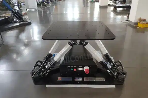
In most real-world 6DOF motion systems, the working principle is implemented through a Stewart platform, also called a hexapod or parallel manipulator. Stewart’s 1965 paper described a mechanism with six degrees of freedom controlled by six motors, originally proposed for flight simulation. That historical link is important, because modern 6DOF motion platforms still follow the same fundamental logic: a fixed base, a moving top platform, and six variable-length legs or actuators connecting the two.
Unlike a serial robot, where axes are stacked one after another, a Stewart platform uses parallel kinematics. That means all six actuators work together on the same moving platform at the same time. This architecture is popular because it can provide high stiffness, compact size, good dynamics, and strong load capacity relative to its footprint. Those are exactly the reasons it appears so often in flight simulators, vehicle simulators, alignment systems, and precision motion control applications.
From an engineering perspective, this is one of the biggest reasons customers choose a 6DOF platform. If you try to build similar motion by stacking multiple linear and rotary axes, errors accumulate, inertia grows, and the structure becomes larger and less elegant. Parallel kinematics solves that problem by making all actuators share the motion task.
How a 6DOF Motion Platform Works Step by Step
The easiest way to understand the 6DOF working principle is to follow the motion command from input to output.

1. The user or host system defines a target pose
The process starts with a target platform pose or motion command. That target may come from simulator software, a motion cueing algorithm, a test script, or a manual control interface. The target is usually expressed as six values: X, Y, Z, roll, pitch, and yaw.
2. The controller calculates the required actuator lengths
This is the heart of the system. The controller takes the desired pose of the top platform and converts it into six leg lengths. This is called inverse kinematics. Instead of asking “where is the platform if I already know the leg lengths?” the controller solves the more useful real-time problem: “what leg lengths do I need to achieve this target position and orientation?” This is why inverse kinematics is central to Stewart platform control.
3. Servo drives move the six actuators simultaneously
Once the target lengths are known, servo motors, electric cylinders, ball screw actuators, or hydraulic actuators drive each leg to the commanded position. Each actuator does not represent only one axis of motion. Instead, each actuator contributes part of the total platform pose. The visible X/Y/Z translations and roll/pitch/yaw rotations appear only after all six actuators move together in the correct combination.
4. Feedback sensors correct the real motion
In a practical 6DOF motion platform, control is closed-loop. Encoders, position sensors, or other feedback devices continuously report actual actuator position and sometimes platform state back to the controller. The controller compares actual motion with commanded motion and corrects errors in real time. This is how the platform maintains accuracy, repeatability, and smooth synchronization across all six actuators.
5. The platform reaches the commanded pose
As the six actuators extend and retract in coordination, the upper platform changes both position and orientation. If one motion command requests pure heave, the six legs change in a pattern that lifts the platform vertically. If the command requests pitch or roll, the actuator pattern changes accordingly. If the command combines translation and rotation—as real simulators often do—the controller superimposes those effects and solves them together.
Why Six Actuators Are Needed
A question I hear often is: why does a 6DOF platform need six actuators? The short answer is that a rigid body in space has six independent motion variables, so the mechanism needs enough controlled inputs to constrain and command those six variables. Stewart’s original work and later kinematics literature are built on this same principle.
That does not mean each actuator “belongs” to one axis. This is where many first-time buyers get confused. In a Stewart platform, actuator motion is coupled. One leg change may contribute partly to heave, partly to roll, and partly to yaw depending on the instant platform pose and geometry. The platform works not because each leg owns one degree of freedom, but because the six legs together can produce a controllable six-dimensional motion space.
Inverse Kinematics: The Real Brain Behind the Motion
If the mechanical structure is the body, inverse kinematics is the brain of the 6DOF working principle. The controller uses the geometric relationship between the base joints, top platform joints, and actuator lengths to compute the exact extension each actuator needs for a target pose. This is why Stewart platforms are often described as elegant but mathematically demanding systems.
For end users, the key point is practical: you do not manually control six legs one by one. You control the desired motion in task space—move up 20 mm, pitch 5 degrees, yaw 3 degrees—and the controller handles the leg-level commands. That separation between user motion command and actuator-level computation is what makes modern 6DOF platforms usable in real industrial and simulator environments.
Control System: Why Smooth Motion Is Harder Than It Looks
6DOF platform may look simple from the outside, but smooth multi-axis motion is a demanding control problem. Each actuator has its own motor, drive, feedback loop, load variation, and dynamic response. The controller has to coordinate all six while respecting limits such as stroke, speed, acceleration, joint angle, and payload. Research and industrial practice both show that Stewart platform performance depends heavily on proper dynamics modeling and control strategy, not just on having six actuators installed.
This is also why two 6DOF platforms with similar appearance can feel completely different in use. The real difference often lies in controller quality, motion planning, servo tuning, structural stiffness, and software integration. In our experience as a motion platform manufacturer, this is one of the most underestimated points in customer evaluation. Buyers often compare only dimensions and payload, while the real user experience depends just as much on control quality and synchronization. This last sentence is my engineering judgment based on how industrial 6DOF systems are designed and evaluated; it is consistent with how authoritative technical sources emphasize controller capability, stiffness, and dynamics.
6DOF vs. Simple Tilting Platforms
Not every platform that moves dramatically is a true 6DOF system. Some systems only provide pitch and roll. Others may add heave and become 3DOF. A true 6DOF platform can independently command all three translations and all three rotations, even though the usable range of each axis depends on geometry, payload, and actuator travel. That distinction matters because many users searching for “6dof working principle” are actually trying to understand whether they need full six-axis capability or a simpler architecture.
If the application only needs vibration, simple tilt, or limited immersive effects, a lower-DOF solution may be enough. But if the goal is higher-fidelity simulation, multi-axis compensation, or full pose control, the working principle of a true 6DOF platform becomes necessary.
Where the 6DOF Working Principle Is Used
The Stewart platform principle has been tied to flight simulation from the beginning. Stewart’s original paper explicitly framed the mechanism as a way to simulate flight conditions for pilot training. Since then, the same architecture has been adopted in vehicle simulators, robotics, precision positioning, machining, force sensing, and advanced testing systems.
In practical terms, the 6DOF working principle is especially valuable in:
- flight simulators
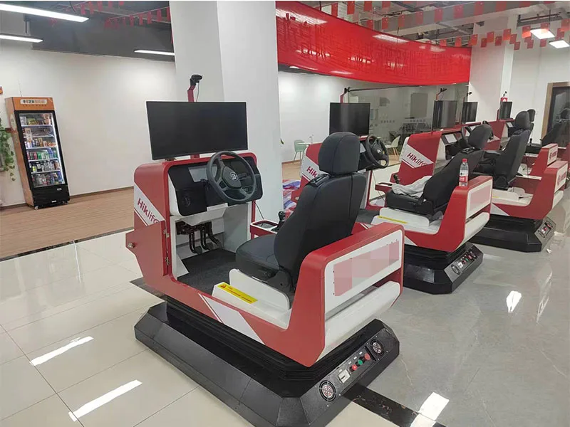
- racing and driving simulators
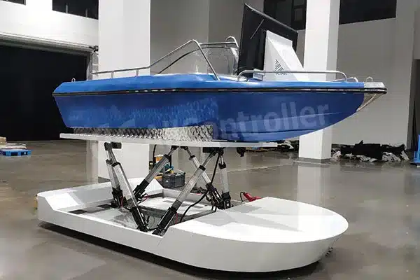
- maritime and vehicle motion simulation
- optical alignment and photonics positioning
- industrial test rigs
- stabilization and compensation systems
- research platforms requiring multi-axis motion reproduction.
Common Misunderstandings About 6DOF Working Principle
“6DOF means the platform can move freely without limits”
Not true. A 6DOF platform can command six independent motion dimensions, but every real machine still has limits in stroke, angle, speed, acceleration, and payload.
“A 6DOF platform is just a platform that tilts in more directions”
Not exactly. True 6DOF includes three linear translations plus three rotations, not only tilt.
“The mechanics alone determine performance”
Also not true. The final result depends on structure, actuators, controller, feedback, software, servo tuning, and integration quality.
“If two platforms have the same payload, they work the same way”
They may follow the same general principle, but performance can differ greatly because of geometry, stiffness, actuator type, control algorithm, and application-specific tuning. This is an engineering inference grounded in how authoritative sources compare parallel kinematics systems and discuss control and dynamics rather than payload alone.
How We Explain It at Allcontroller
At Allcontroller, when customers ask about the 6DOF working principle, they are usually not asking for a textbook answer. They are trying to decide whether a 6DOF platform can really deliver the motion effect, control accuracy, software integration, and payload capacity their project needs. That is a much more practical question. The principle is universal, but the execution is application-specific. A simulator project, a test rig, and a research platform may all use the Stewart platform concept, yet require very different actuator sizing, controller strategies, safety logic, and upper-platform design. This application-specific conclusion is our manufacturer perspective, and it aligns with the way authoritative sources distinguish architecture, control, and application requirements.
That is why, in real procurement, understanding the working principle is only the first step. The next step is translating motion requirements into an actual platform specification: payload, center of gravity, required strokes, required rotation angles, motion bandwidth, control method, and software/API integration. That is where engineering support matters much more than generic marketing language.
Conclusion
The 6DOF working principle is straightforward once you strip it down to fundamentals: a rigid body has six independent motions, a Stewart platform uses six coordinated actuators in parallel to control those motions, inverse kinematics converts the desired pose into leg lengths, and a closed-loop controller keeps the real platform synchronized and accurate. That combination is why 6DOF motion platform remain the preferred architecture for many simulator, test, and precision motion applications.
If you are evaluating a 6DOF motion platform for simulation, testing, or a custom project, the smartest next step is not just to ask for price. It is to define the real motion task first. Once the required pose range, payload, control method, and application scenario are clear, the right 6DOF platform architecture becomes much easier to specify. That is usually where a good project stops being abstract and starts becoming buildable.
What is the 6DOF working principle?
Is a Stewart platform the same as a 6DOF platform?
Why does a 6DOF platform need six actuators?
What role does inverse kinematics play in 6DOF motion?
Where are 6DOF motion platforms commonly used?
References:
1. Six degrees of freedom——Wikipedia
2. A Platform with Six Degrees of Freedom——Sage Journals
3. Simulate Motion in Six Degrees of Freedom (6DOF)——MathWorks
4. Stewart platform——Wikipedia