Finite element analysis (FEA) uses mathematical approximation to simulate real physical systems (geometry and load conditions). Using simple and interacting elements (i.e. units), a real system with infinite unknowns can be approximated with a finite number of unknowns.
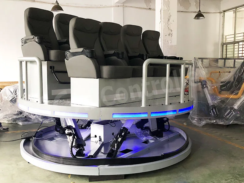
Finite element analysis builds a three-dimensional model of the six-degree-of-freedom platform (such as using software such as PRO/E, SolidWorks, etc.), divides it into grid units, and solves the platform’s stress, strain, natural frequency and other characteristics based on material properties, load conditions and other parameters. For example, modal analysis can reveal the vibration mode and natural frequency of the structure to avoid resonance with external excitation.
Effect
Structural strength and stiffness verification
Through static analysis, the stress distribution and deformation of the platform under extreme load are evaluated. For example, the maximum stress of key components such as upper and lower platforms and electric cylinder hinges is analyzed to see whether it exceeds the material strength limit to prevent structural fracture or plastic deformation.
Dynamic characteristics optimization
Modal analysis is the focus of finite element analysis, which can determine the natural frequency and vibration mode of the platform. For example, the fundamental frequency of a platform is concentrated in 30~55Hz. If the frequency of external excitation (such as motor vibration) is close to this range, it may cause resonance, and the risk needs to be avoided by adjusting the structure or material. Studies have shown that the stiffness of connecting parts (such as universal joints and ball joints) has a significant impact on the natural frequency and needs to be optimized.
Lightweight design and material selection
Through stress distribution results, redundant material areas can be identified to achieve lightweight design. For example, finite element analysis of robot components can optimize the thickness of structural parts or replace high-specific strength materials to reduce the weight of the platform while maintaining the load-bearing capacity.
Fatigue life prediction
Combined with stress cycle analysis under alternating load conditions, the fatigue life of key components (such as servo electric cylinders and hinges) is predicted to provide a basis for maintenance cycles.
Safety and reliability assurance
Finite element analysis can simulate extreme working conditions (such as emergency braking and random motion) and verify the stability of the platform under complex motion. For example, dynamic simulation can be used to verify the anti-deformation ability of a six-degree-of-freedom platform in compound motions such as pitch and yaw to ensure its reliable operation in training simulators or industrial applications.
Finite element analysis calculation
The basic idea of finite element method : Through the node displacement of the unit, the displacement field of the entire unit can be obtained using the interpolation function. Next is the derivation of the unit stiffness matrix and load vector. According to the assumed displacement function, the unit stiffness matrix K^e and load vector P^e can be derived using the equilibrium condition and the minimum potential energy principle. After that, the unit stiffness matrix is assembled to obtain the total stiffness matrix of the structure, and the total equilibrium equation of the structure is obtained:
[K]{∅}=[P]
Where K is the total stiffness matrix, 8 is the node displacement of the overall structure, and P is the vibration acting on the entire structure. Finally, a simplified set of equilibrium equations is obtained according to the boundary conditions of the problem to be solved, and the node displacement θ is obtained through the simplified set of equilibrium equations. Based on the obtained node displacement θ, the strain and stress of the unit can be calculated through the relevant formulas of solid mechanics.
Static strength design criteria:
The design load of a structure is equal to the service load multiplied by the safety factor. When the ultimate bearing capacity of the structural material is greater than or equal to the design load of the structure, or when the ultimate stress of the structural material is greater than or equal to the stress caused by the design load of the structure, the structure is considered safe. The expression is:

- Pu : Ultimate load (material limit load-bearing capacity)
- Pd : Design load
- f: Safety factor
- Pe : Service load (operational load)
- [σ]: Ultimate stress
- σd: Structural stress induced by the design load

PowerLab dynamics simulation is to ensure the safe and reliable operation of the motion platform. We have conducted a lot of analysis and calculation on key components, and carried out entity modeling, model optimization, finite element analysis, and determined the conclusions.
According to the results of PowerLab dynamics analysis, the electric cylinder is selected and calculated to obtain the theoretical maximum thrust of the electric cylinder. This thrust is used as the basis for finite element analysis of structural parts other than the upper platform. Regardless of whether the electric cylinder and the motor are directly connected or parallel, it should be ensured that the motor power can meet various motion requirements. It is strictly forbidden for the motor to be in an overload state for a long time during operation.

Modal Analysis
In order to make the six-freedom robot have good dynamic performance in work, the finite element model of the robot is established by finite element software, and the typical posture is selected for modal analysis. The finite element method and vibration theory are used to perform modal analysis on the overall mechanism. The analysis is carried out according to two schemes: ANSYS and ADAMS.
ANSYS uses the finite element method to solve the mode. Using the variational principle, the stiffness matrix and mass matrix of each unit are formed, the overall stiffness matrix is assembled, the boundary conditions are set, and the vibration equation theory is used to solve the mode. ADAMS solves the mode based on the multi-body dynamics method. The vibration equation in the Euler-Lagrange theory is used to solve the mode.
The two methods are essentially the same, and must have stiffness and mass matrices. However, the methods of forming the matrices are different. The variation law of the natural frequency of the robot in typical positions and postures is obtained, and the natural frequencies and vibration modes of the two schemes are analyzed and synthesized. The weak links of the overall structure are analyzed, and finally a method to improve the dynamic performance of the motion platform and a structural design improvement plan are proposed.
Structural dynamics is the study of the relationship between structure, load and dynamic response of a structure under dynamic load. Structural dynamics can generally be divided into the following three major problems:
- Given the structure of the research object and the load it bears, find the dynamic response;
- Given the structure and dynamic response of the research object, calculate the load it bears;
- Given the loads and dynamic responses of the research object, find the structure.

Six-degree-of-freedom finite element analysis has shown significant advantages in the design of complex motion platforms due to its multi-physics field coupling and high-precision numerical simulation capabilities. By integrating statics, dynamics and modal analysis, this method can not only accurately evaluate the structural strength and stiffness under extreme loads, but also reveal the dynamic characteristics of the system to avoid resonance risks; its lightweight design optimization function can intelligently identify the distribution of redundant materials and achieve a scientific balance between strength and weight; at the same time, based on multi-condition fatigue life prediction and complex motion stability verification, it provides data support for the platform’s full life cycle safety. Compared with traditional experimental methods, six-degree-of-freedom finite element analysis breaks through the limitations of physical prototypes, significantly shortens the R&D cycle through multidisciplinary collaborative simulation, and supports full-process closed-loop design from structural optimization, material selection to dynamic performance improvement. This technical path that deeply integrates theoretical models with engineering practice not only reduces the cost of trial and error, but also promotes the continuous evolution of motion platforms towards high reliability and high energy efficiency, becoming a core enabling tool for the innovative design of modern high-end equipment.
For some large-scale six-degree-of-freedom motion system projects, it is very necessary to perform finite element analysis. If your project cannot be analyzed by yourself, you are welcome to contact us to obtain a free finite element analysis solution.