I’ve spent years working on motion platform systems for simulator applications — and the Stewart platform is the one piece of hardware that comes up in almost every serious conversation about flight training fidelity.

Not because it’s trendy. Because it works. And because, so far, no other motion architecture has come close to matching its combination of stiffness, payload capacity, and six-axis precision in a compact mechanical package.
But I’ve also seen this system misunderstood, undersized, and misconfigured more times than I’d like to count. So in this guide, I want to break it down properly — the engineering logic, the regulatory context, the real performance constraints, and the decisions that actually matter when you’re specifying or integrating a flight simulator motion system.
Table of Contents
What Is a Stewart Platform?
Let me start with the basics, because the name “Stewart platform” gets used loosely in ways that sometimes obscure what’s actually being described.
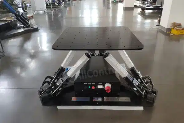
A Stewart platform is a type of parallel manipulator that has six prismatic actuators — commonly hydraulic jacks or electric linear actuators — attached in pairs to three positions on the platform’s baseplate, crossing over to three mounting points on a top plate. All 12 connections are made via universal joints. Devices placed on the top plate can be moved in the six degrees of freedom in which it is possible for a freely-suspended body to move: three linear movements (lateral, longitudinal, and vertical) and three rotations (pitch, roll, and yaw).
In plain terms: six legs, two plates, twelve joints, and the ability to move any object mounted on the top plate through every possible direction of motion in three-dimensional space.
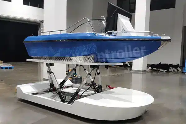
The Stewart platform design is extensively used in flight simulators, particularly in the full flight simulator which requires all six degrees of freedom. In this role, the payload is a replica cockpit and a visual display system, normally of several channels, for showing the outside-world visual scene to the aircraft crew being trained.
That’s the setup in essentially every Level C and Level D Full Flight Simulator operating in commercial aviation today.
A Quick Note on the Name
This specialized six-jack layout was first used by V.E. (Eric) Gough of the UK and was operational in 1954, the design later being publicized in a 1965 paper by D. Stewart to the UK Institution of Mechanical Engineers. In 1962, prior to the publication of Stewart’s paper, American engineer Klaus Cappel independently developed the same hexapod. Klaus patented his design and licensed it to the first flight simulator companies, and built the first commercial octahedral hexapod motion simulators.
I raise this not for a history lesson, but because if you’re in a technical procurement conversation and someone refers to a “Gough-Stewart platform” or a “hexapod” — they mean exactly the same thing. The terminology inconsistency is a real source of confusion in RFQ documents and spec sheets.
How It Works: The Mechanical Logic
A Stewart platform is built around two plates — one fixed, one movable — linked by six adjustable-length actuators. Because the actuators operate in parallel, any change in length affects the platform as a whole, allowing the upper plate to translate or rotate with remarkable stiffness and accuracy. This parallel approach contrasts sharply with the serial chain of joints used in traditional robot arms.
That parallel architecture is the core engineering advantage. Think of it this way: in a serial robot arm, each joint carries the full load of everything beyond it. In a Stewart platform, all six actuators share the load simultaneously. That’s why it can carry a full cockpit replica — sometimes weighing several thousand kilograms — and still deliver sub-millimeter positional accuracy at high dynamic bandwidth.
The Inverse Kinematics Problem
The real challenge in a Stewart platform lies in the math, not the metal. To hit a specific pose, the controller must solve the inverse kinematics equations — figuring out the exact length each actuator needs right now — dozens or hundreds of times per second. That demands fast processing, tight feedback loops, and software that’s been thoroughly tested for edge cases.
This is worth pausing on. The mechanical structure of a Stewart platform is relatively straightforward to fabricate. The hard part is the control system — and specifically, the real-time inverse kinematics solver running continuously in the background.
From my own experience: we’ve seen projects where the mechanical build was excellent but the controller couldn’t maintain loop rates above 500 Hz, which showed up as perceptible lag and jitter in the cockpit. Pilots noticed immediately. In training simulators, that kind of control-induced artifact isn’t just uncomfortable — it’s a training fidelity problem.
The Role of Motion Cueing: Washout Filters Explained
Here’s the part most people outside the flight simulation industry don’t fully appreciate.
A Stewart platform has a physically limited workspace. In practice, most full-flight simulator platforms have actuator strokes of roughly ±300–600mm and angular travel of roughly ±25–30° per axis. That sounds like a lot — until you realize that a real aircraft can sustain acceleration in one direction for minutes at a time, while your platform can sustain it for about half a second before hitting a mechanical limit.
The solution to this fundamental constraint is the Motion Cueing Algorithm (MCA) — historically implemented as a Washout Filter.
The fidelity of a moving-base flight simulator is greatly dependent on the washout algorithm of the Stewart platform, which may reach the workspace limits when simulating the aircraft recovery from upset conditions.
The washout filter works by exploiting a psychophysical property of the human vestibular system: the inner ear detects changes in acceleration (jerk), not sustained acceleration. After delivering an initial motion impulse that triggers the correct vestibular response, the filter gradually returns the platform to its neutral position — so slowly that the pilot doesn’t perceive the return movement, only the initial cue.
It’s a form of controlled sensory deception, engineered to be imperceptible. When it’s done well, a pilot in a simulator feels like they’re in continuous flight. When it’s done poorly, they feel nauseous and confused.
Why the Classical Washout Filter Has Limits
The classical filter-based washout algorithm is the most widely used motion cueing algorithm for simulation of motion effects in a flight simulator. All FAA Part 121 air carriers are required to implement UPRT regulations on flight simulators of Level C or above. However, when approaching or exceeding the normal flight envelope, it is difficult to simulate the continuous movement and rapid change of the recovery from the upset as in a real aircraft due to the limited workspace of the flight simulator. If the motion cues received by pilots are quite different from the real flight, it may lead to a negative transfer effect — meaning that training on a flight simulator leads pilots to conduct incorrect responses and/or misunderstand the behavior of the aircraft in real flight.
This is the core tension in flight simulator motion system design: the workspace is inherently constrained, but the training scenarios — particularly Upset Prevention and Recovery Training (UPRT) — require rapid, high-magnitude motion cues to be effective.
Recent research has addressed this directly. A 2025 arXiv paper by Zhao et al. proposes a Switchable Model Predictive Control (S-MPC) based Motion Cueing Algorithm, which outperforms the classical washout filter approach by 42.34% and 65.30% respectively under Average Absolute Scale evaluation criteria during horizontal stall UPRT simulations.
What this tells us: the state of the art in motion cueing is actively evolving, and the control software matters as much as the mechanical hardware. A Flight Simulator Stewart Platform with a poorly tuned MCA is significantly less effective than one with an optimized algorithm — even if the mechanical specs are identical.
The Role of Motion Cueing: Washout Filters Explained
I want to be precise here, because I’ve seen this misrepresented in vendor literature.
FAA 14 CFR Part 60 defines the qualification levels for Flight Simulation Training Devices (FSTDs):
| Device Level | Motion Requirement | Typical Use |
|---|---|---|
| BATD (Basic ATD) | None | Instrument procedures, PPL |
| AATD (Advanced ATD) | None | Complex procedures, IR |
| FTD Level 4–7 | None (Level 4–6); Optional (Level 7) | Systems training, partial task |
| FFS Level A | Some motion | Basic airline training |
| FFS Level B | Motion required | Takeoff/landing, transitions |
| FFS Level C | 6DOF motion required | Type rating, recurrent |
| FFS Level D | 6DOF motion + enhanced | Highest fidelity, zero-flight-time type ratings |
A moving-base flight simulator generally uses the Flight Simulator Stewart Platform as its source for motion to simulate the aircraft movement in the air. At Level C and D, there is no alternative to a six-axis motion system that meets the FAA’s frequency response, phase delay, and positional accuracy requirements.
This has real commercial implications. Airlines operating under FAA Part 121 must conduct recurrent training and proficiency checks in Level C or D simulators. If your simulator’s motion system can’t meet these specifications, those training hours don’t count toward regulatory requirements.
The Role of Motion Cueing: Washout Filters Explained
Research published in the Journal of Guidance, Control, and Dynamics found that the bandwidth of the motion system had a significant effect on pilot performance and control behavior. Results indicate that the motion cues were barely used at all in conditions with low bandwidth, and that participants relied on visual cues to generate lead to perform the control task.
That finding has direct implications for how you specify a motion system. Bandwidth — not just stroke length — determines whether pilots actually use the motion cues or disregard them. A platform with generous stroke but sluggish dynamic response is, in training terms, nearly equivalent to a fixed-base simulator.
Electric vs. Hydraulic Actuators: The Technology Choice
Most people specifying a flight simulator Stewart platform face one major technology decision early on: electric or hydraulic actuation?
Here’s how I frame this in project conversations:
Hydraulic systems have been the industry standard for large commercial FFS for decades. They offer high force density — meaning they can push harder for their size — which matters when you’re moving a cockpit replica that may weigh 3,000–8,000 kg. The downside: hydraulic systems require a dedicated power unit, oil management, temperature control, and regular seal maintenance. For a facility running simulators 18+ hours per day, that maintenance burden accumulates.
Electric servo systems have improved dramatically in the last decade. Modern electric linear actuators now match hydraulic performance for most FFS payload ranges, with several additional advantages: cleaner installation (no hydraulic fluid risk), faster position control loop rates (enabling higher bandwidth), lower operating cost, and quieter operation. For simulator facilities, the noise factor matters more than people expect — a hydraulic power unit is loud, and that bleeds into the training environment.
At Allcontroller, the majority of our new motion platform builds for simulator applications now use electric servo actuators. Not because hydraulic doesn’t work — it clearly does — but because the total cost of ownership over a 10-year operational horizon typically favors electric, and the control performance is comparable.
The key is actuator quality and the servo drive system. An electric Stewart platform with cheap actuators and a generic motion controller is not equivalent to one with precision ball-screw servo cylinders and a purpose-built real-time controller. The mechanical spec and the control system spec are inseparable.
Key Performance Parameters: What to Specify
When I’m reviewing a Flight Simulator Stewart Platform specification for a flight simulator application, these are the parameters I focus on most carefully:
1. Payload Capacity (Static vs. Dynamic)
Static payload rating tells you what the platform can hold at rest. Dynamic payload — accounting for the inertial forces generated by six-axis acceleration — is lower and more relevant to actual simulator operation. I use a rule of thumb: specify a platform with a dynamic payload rating at least 1.5× your actual cockpit assembly weight.
2. Actuator Stroke
Typical commercial FFS platforms have individual actuator strokes in the range of ±300mm to ±600mm. More stroke gives you larger translational workspace and enables more pronounced initial motion cues — beneficial for UPRT scenarios. But longer stroke also increases the structural height of the platform, which has facility ceiling-height implications.
3. Velocity and Acceleration
These determine dynamic response — how quickly the platform can transition from neutral to full displacement. For UPRT training, you need high angular acceleration capability (typically ≥500°/s² in roll) to reproduce the vestibular onset cues of a real upset event.
4. Control System Bandwidth
As the FAA-referenced research showed, low bandwidth fundamentally undermines training effectiveness. For a flight simulator motion system, I look for a closed-loop bandwidth of at least 10–15 Hz for the motion base, with actuator control loops running at 1–2 kHz or faster.
5. Latency (End-to-End)
Total motion-to-display latency must be below approximately 100ms to avoid inducing simulator sickness. Motion system contribution to that latency budget should be below 20–30ms. This is where the controller architecture matters significantly — embedded real-time controllers outperform PC-based controllers in deterministic latency.
6. Interface Compatibility
The full integration with a flight simulation software environment — such as Microsoft Flight Simulator, X-Plane, or a military DCS — requires careful attention to the data interface layer. The motion system controller needs to ingest aircraft state data (accelerations, angular rates, attitude) in real time, typically via UDP, CAN, or EtherCAT protocols, and execute the inverse kinematics and MCA loop faster than the simulation frame rate.
Key Performance Parameters: What to Specify
Mistake 1: Over-prioritizing stroke, under-prioritizing bandwidth. I’ve seen simulator specs where the operator requested maximum actuator stroke to “get the most motion possible,” but the control system bandwidth was too low to use it effectively. The result was a sluggish platform that felt artificial. Shorter stroke with high bandwidth is almost always more effective.
Mistake 2: Treating the MCA as a black box. The washout filter parameters are not a set-and-forget configuration. Every cockpit configuration, payload distribution, and training task requires tuning. Operators who don’t have access to the MCA configuration — or who don’t understand how to adjust it — are leaving significant training fidelity on the table.
Mistake 3: Ignoring center-of-gravity implications. The cockpit replica’s center of gravity (CG) relative to the top plate dramatically affects the dynamic load distribution across the six actuators. A high CG with a cantilevered visual display system can produce actuator overload conditions during high-acceleration maneuvers. This is something we always model during the design phase — never assume the static payload spec alone tells the full story.
Mistake 4: Underspecifying the facility. A full-flight simulator with a Stewart platform requires significant floor area (typically 6m × 6m minimum) and ceiling height (typically 4–5m clear). I’ve seen projects where a technically correct platform was ordered, then couldn’t be installed because the facility plan didn’t account for the full displacement envelope.
How Allcontroller Approaches Flight Simulator Stewart Platform Systems
At Allcontroller, we manufacture motion platform systems with a particular focus on the control layer — because that’s where most of the real performance differentiation happens.
Our flight simulator platform systems are built around:
Precision electric servo actuators with integrated position feedback (encoder resolution ≤1μm), rated for continuous dynamic operation
Real-time motion controllers with closed-loop rates at 2kHz and end-to-end latency under 5ms, running purpose-built inverse kinematics firmware
Configurable MCA modules — we give operators access to washout filter parameters and, for advanced applications, MPC-based motion cueing options
Open interface design — native UDP, EtherCAT, and CAN support for compatibility with X-Plane, Prepar3D, DCS World, and custom simulation environments
Structural design review — every project includes a CG analysis and actuator load-distribution simulation before fabrication
We work with simulator integrators, flight schools, defense training contractors, and R&D teams. And I’ll say directly: we don’t recommend a 6DOF Stewart platform for every customer. If your application is a VR entertainment simulator or a single-pilot light aircraft trainer not targeting FAA certification, there are lower-complexity options that deliver better ROI.
But if you’re building something that needs to replicate the vestibular reality of a real aircraft at certification-relevant fidelity — this is the system, and it needs to be done right.
What is a Stewart platform in a flight simulator?
Why do flight simulators use a Stewart platform instead of other motion systems?
What is a washout filter and why does it matter?
What FAA level requires a Stewart platform?
Electric or hydraulic actuators — which is better for a flight simulator Stewart platform?
How long does it take to integrate a Stewart platform into a flight simulator?
Can I build a flight simulator Stewart platform myself?
References:
1. Stewart, D. “A Platform with Six Degrees of Freedom.” Proceedings of the Institution of Mechanical Engineers, 1965.
2. Zhao, J. et al. “Six-DoF Stewart Platform Motion Simulator Control using Switchable Model Predictive Control.” arXiv:2503.11300, March 2025.
3. Burki-Cohen, J., Go, T.H., and Longridge, T. “Flight Simulator Fidelity Considerations for Total Airline Pilot Training and Evaluation.” AIAA Modeling and Simulation Technologies Conference, 2001.
4. FAA 14 CFR Part 60 – Flight Simulation Training Device Initial and Continuing Qualification and Use.
5. Pool, D.M. et al. “Influences of Simulator Motion System Characteristics on Pilot Control Behavior.” Journal of Guidance, Control, and Dynamics, 2012.
6. Wang, L. et al. “Model Predictive Control Based Washout Algorithm Design for Flight Simulator Upset Prevention and Recovery Training.” Aerospace (MDPI), Vol. 10, No. 10, 2023.
7. Wikipedia. “Stewart Platform.” Accessed 2025.
8. Actuonix. “Understanding the Basics of Stewart Platforms and Their Applications.” actuonix.com, 2025.