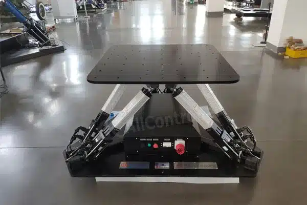
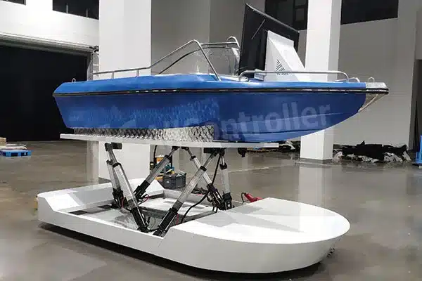
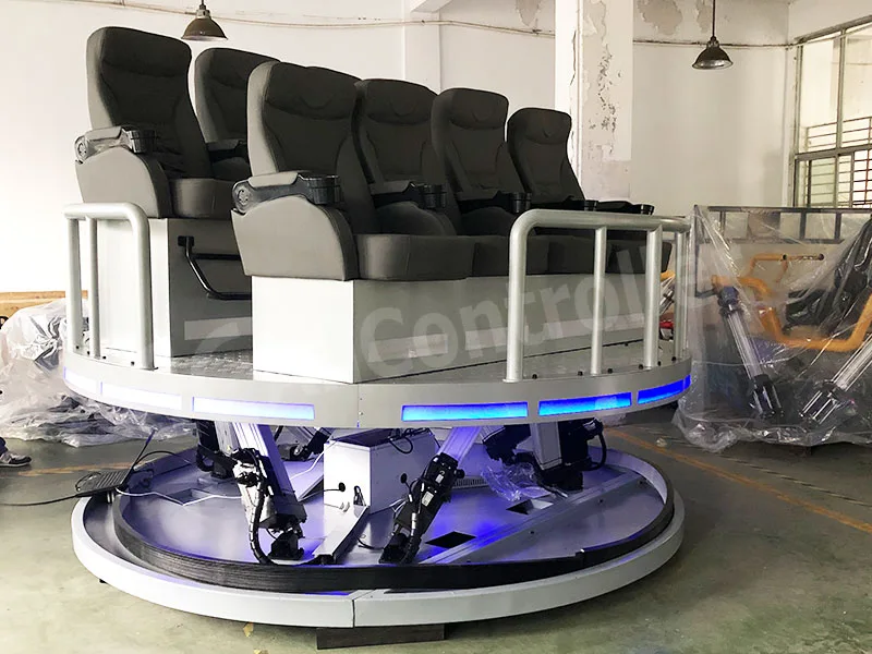
An industrial 6 axis motion control platform is a sophisticated multi-degree-of-freedom system—typically utilizing hexapod or serial kinematics—to provide precise control over X, Y, Z, Pitch, Roll, and Yaw axes for complex simulation and industrial testing. Unlike simpler systems, a true 6 axis motion control platform requires the synchronized integration of high-speed motion controllers, precision actuators, and complex inverse kinematic algorithms to handle spatial movements in real-time.
For engineers, the ultimate goal is achieving “dynamic fidelity,” ensuring the platform’s mechanical response perfectly mirrors command signals without introducing parasitic vibrations, structural lag, or mathematical errors that could compromise sensitive R&D data or simulation realism.
Table of Contents
What people usually really want when they search this keyword
When someone types “6 axis motion control platform,” they’re rarely shopping for a concept. They’re usually stuck on one of these:
- “Why does my platform hit the target but never settles?”
- “Why does accuracy look fine at low speed, then collapse at production speed?”
- “Why do I keep fighting cross-axis coupling and retuning forever?”
- “How do I write a spec that vendors can’t hand-wave?”
And honestly—every “mystery” problem above maps back to a short list of design challenges you can address upfront.
The Engineer’s Reality: Why 6 axis motion control platform is More Than "Six Motors"
I’ve stood floors where a client’s self-built rig was shaking so violently it looked like it would tear itself apart. They had the right motors and the right power, but they were missing the “soul” of the system: the control logic.
Designing a 6 axis motion control platform isn’t just about bolting six actuators together. It is about managing the chaotic relationship between high-speed math and heavy-duty physics. When you deal with 6 degrees of freedom, you are fighting three main “ghosts” in the machine: Kinematic Singularities, Control Latency, and Structural Resonance.
Challenge 1: Stiffness and structural modes
What goes wrong?
You can hit the commanded pose and still fail the job because the structure rings like a bell. In high-precision work, settling time is often the KPI that quietly decides throughput and yield.
Parallel mechanisms (hexapods) are often pursued because of higher rigidity / strength-to-weight advantages compared with serial architectures in many configurations.
But even then, real platforms still suffer from resonances caused by joint compliance, mounting interfaces, payload inertia, and cable forces.
What we do in practice
Design for stiffness where it matters: short load paths, stiff base mounting, and payload interface plates that don’t “oil-can.”
Treat the payload as part of the machine: inertia and CoG placement can move resonant frequencies dramatically.
Use jerk-limited trajectories (S-curves) to avoid exciting modes.
Measure and model: even a simple modal test (impact hammer + accelerometer) can save weeks of retuning.
If you want an academic anchor: parallel-machine-tool literature repeatedly frames performance around stiffness, dynamics, calibration, and industrial barriers—because that’s where platforms win or lose in real deployments.(Reference reading: A review of parallel kinematic machine tools: Design, modeling, and applications)
Challenge 2: Kinematics, workspace “weirdness,” and singularities
What goes wrong
Parallel kinematics platforms don’t behave uniformly across the workspace. Near boundaries, the Jacobian can become ill-conditioned (you feel it as “sudden sensitivity,” force spikes, or loss of controllability).
What we do
Define a “golden workspace”: specify where full performance is guaranteed (not just reachable).
Use conditioning metrics during design: plan geometry so typical operating poses are far from singular regions.
Enforce software workspace limits that are tighter than mechanical limits (the boring safety guardrail that prevents expensive crashes).
Modern reviews of parallel kinematic systems emphasize exactly these modeling and performance-evaluation metrics (kinematic/dynamic, error analysis, calibration) as core to practical deployment.
Challenge 3: Control architecture and timing
What goes wrong
If axis loops aren’t synchronized (or if your real-time bus jitters), you don’t get “6 axis motion control platform”—you get six axes arguing in public.
What we do
Control loop hierarchy: current/torque → velocity → position → pose (outer loop) with clearly defined bandwidths.
Hard real-time communication: deterministic EtherCAT-class timing (or equivalent) and careful cycle-time budgeting.
Feedforward: velocity/acceleration feedforward reduces lag so you don’t “chase” the pose.
Cross-coupling compensation where relevant: because true pose control is inherently coupled.
If you ever wondered why research papers spend so much ink on kinematics/dynamics formulations (Jacobian, time derivatives, actuator dynamics, friction), it’s because these terms show up as real tracking errors and force spikes in the plant.
Challenge 4: Accuracy vs repeatability, and why calibration isn’t optional
Here’s a slightly uncomfortable truth from the shop floor:
Many systems are repeatable long before they are accurate. That gap is where calibration lives.
Industrial standards (ISO 9283) explicitly frame performance around things like position stabilization time, overshoot, drift, and more—because these are the real-world behaviors users must test and compare.
What we do
Define what “accuracy” means: absolute pose accuracy in world coordinates? or relative repeatability around a working point?
Plan calibration early:
geometric calibration (link lengths, joint offsets),
compensation models (lookup tables / error maps),
verification plan (metrology equipment + acceptance poses).
Make calibration sustainable: production systems need recalibration strategy, not a one-time lab miracle.
Recent calibration surveys for Stewart/hexapod-class machines underline that calibration identifies error factors and adds correction to make outputs reliable/predictable—exactly the pain customers feel in the field.
And error compensation / calibration methods continue to be an active research area because it materially improves positioning precision.
Challenge 5: Thermal drift and “small forces”
What goes wrong
In high-precision environments, heat and tiny parasitic forces (cable drag, air hoses, moving coolant lines) create slow drift. You can hit spec at 9:00 AM and fail it at 3:00 PM.
What we do
Thermal symmetry: design so heat paths don’t bend the structure in one direction.
Warm-up protocol (seriously): define a stable state before acceptance testing—ISO-style testing approaches commonly assume steady-state conditions.
Cable discipline: routing, strain relief, and drag-chain design are “unsexy,” but they’re precision features.
Challenge 6: Safety, fault handling, and industrial acceptance
What goes wrong
A platform can be brilliant in the lab and unacceptable in procurement because no one can verify performance consistently.
What we do
Write measurable acceptance tests:
pose repeatability at defined points,
path accuracy (if trajectory matters).
Fault strategy
limit enforcement (software + hardware),
actuator error handling,
safe-stop behavior under power/network faults.
ISO 9283 exists for a reason: it defines performance characteristics and test methods so users can compare systems with less ambiguity.
From Concept to Customization: The Allcontroller Approach
Every customized motion system we build starts with a conversation about the “Worst Case Scenario.” What is the heaviest load? What is the fastest move?
We’ve learned—often the hard way, through years of trial and error—that a platform is only as good as its weakest joint. Whether it’s choosing the right spherical bearings to eliminate backlash or fine-tuning the PID loops for a specific payload, the “magic” is in the details that you don’t see on a datasheet.
FAQ: 6 Axis Motion Control Platform
What is the difference between Serial and Parallel 6 Axis Motion Control Platform?
A serial platform (like a robotic arm) stacks axes one on another; an error in the first axis is multiplied by the rest. A parallel platform (Hexapod) connects all six actuators to one base and one top, distributing the load and averaging out mechanical errors for much higher precision.
Can I use 6 Axis motion Control Platform for high-frequency vibration testing?
Yes, but only if the system’s Natural Frequency is significantly higher than the test frequency. For high-frequency work, we recommend low-mass, high-stiffness carbon fiber struts and high-speed servo drives.
Why is “Washout Filtering” important in 6 Axis Motion Control Platform?
In flight or driving sims, the platform has limited travel. Washout Filters are algorithms that return the platform to its center position so slowly that the user doesn’t feel it, “resetting” the workspace for the next big move.
A Final Thought for the Project Lead
Building a 6 axis motion control platform is a journey of managing compromises. It’s easy to get lost in the “specs,” but I always tell our clients: focus on the Repeatability. In an industrial environment, moving once is easy; moving exactly the same way 100,000 times under load is the true test of engineering.
What is the “bottleneck” in your current motion project? If you’re dealing with jitter or synchronization issues, let’s look at your control architecture together. I’m happy to share our factory’s internal “Tuning Guide” to help you stabilize your system.